[vc_row css=”.vc_custom_1566250259052{margin-top: 0px !important;margin-bottom: 0px !important;padding-top: 0px !important;padding-bottom: 0px !important;}”][vc_column width=”2/3″][vc_column_text]What do successful distillation scale-up projects have in common? Project managers must understand and determine five key design elements for project success. Cost, chemical interactions and equipment needs change in a non-linear fashion as increased output is required. Qualified engineers should consider the following critical steps:
- Vapor-Liquid Equilibrium
- Column Operating Objectives
- Operating Pressure
- R/Dmin and Nmin and Feed stage estimation
- Diameter and Height of the Column
Our distillation design expert, Terry Tolliver, walks through each of these practical distillation column design & sizing steps below.[/vc_column_text][vc_row_inner][vc_column_inner width=”2/3″][vc_column_text]
Contact us today at 314-806-1678 to talk with and EPIC engineer regarding an upcoming distillation systems project.
[/vc_column_text][/vc_column_inner][vc_column_inner width=”1/3″][vc_btn title=”Contact Us” style=”custom” custom_background=”#3877bf” custom_text=”#ffffff” link=”url:https%3A%2F%2Fepicmodularpro.wpengine.com%2Fcontact|||”][/vc_column_inner][/vc_row_inner][/vc_column][vc_column width=”1/3″][vc_empty_space height=”20px”][vc_widget_sidebar sidebar_id=”secondary”][/vc_column][/vc_row][vc_row][vc_column][vc_tta_tabs][vc_tta_section title=”Design Steps” tab_id=”Design”][vc_column_text]
Introduction to Distillation Column Design:

Vapor-Liquid Equilibrium
The starting point upon which all column design is based is to accurately determine the relative volatility of the key components to be separated. Using a mass and energy balance simulation program, such as Aspen Hysys®, the user must set up the basis of the simulation by selecting an appropriate fluid package and the components present in the feed. Activity coefficients, estimated by the program or provided by the user, are used to relate non-ideal component interactions.
Column Operating Objectives
The first step in column design is specifying the column operating objectives. These are defined by a primary product composition and an optimal recovery of the product from the waste, recycle or less important by-product stream. These specifications should be in terms of the heavy key impurity in the top stream and the light key impurity in the bottom stream.
Operating Pressure
Once the top and bottom stream compositions are specified, the dew point of the top stream and the boiling point of the bottom stream may be determined at various pressures. An operating pressure should be selected that allows acceptable temperature differences between available utilities because the overhead vapor must be condensed and the bottom liquid reboiled.
Cooling tower water used for condensing is typically supplied at 90 degF (worst case summer temperature) and returns at 120 degF to avoid condenser fouling. City water, river water or chilled water may be available to provide a lower coolant temperature. Steam, hot oil or electrical heaters are typical utilities used for reboiling. Steam supply pressure determines the available heating temperature, with a range of 30 psig steam at 250 degF and higher pressure steam up to 500 degF. Hot oil or electrical heaters are often used to provide a range of temperatures above 400 degF.
When possible, atmospheric or pressure operation of the column is preferred in order to avoid requiring a vacuum system. However, another consideration is component heat sensitivity, which may require lower pressure operation to avoid fouling, product discoloration or decomposition. Often the relative volatility is also improved at lower pressures.
R/Dmin & Nmin and Feed Stage Estimation
Using the simulation program, shortcut procedures based upon total reflux operation allow the minimum reflux ratio (R/Dmin) and minimum number of ideal separation stages (Nmin) to be determined. Using an actual reflux ratio of 1.2 times the minimum reflux ratio will allow an optimal number of stages to be estimated as well as an appropriate feed stage.
Rigorous simulation of the distillation at a given feed rate and composition may now be accomplished by specifying the following: top and bottom product compositions, number of stages, feed stage, and top and bottom pressure. (Pressure drop across the column may be initially estimated as 0.1 psi per stage.)
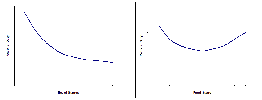
Parametric cases of this simulation should be used to verify the estimated number of stages and feed location. Add and subtract stages from both the stripping and rectifying section of the column. Do this until the required reflux ratio becomes approximately 1.2 times the minimum reflux ratio, or the trade off between utility usage and the number of stages appears optimal for the specific column. As more total stages are used, the required reboiler duty will decrease until there are diminishing returns, as illustrated in Figure 1a. As the feed stage is varied, there will be a minimum reboiler duty required as shown in Figure 1b.

Diameter and Height of the Column
At this point, the distillation process is well defined, leaving the column diameter and height to be determined. The chosen design case from the simulation program provides the internal liquid and vapor flows and their physical properties for every stage of the column. The column diameter is chosen to provide an acceptable superficial vapor velocity, or “Fs factor”. This is defined as vapor velocity (ft/sec) times square root of vapor density (lb/ft3), and liquid loading defined as volumetric flow rate (gal/min), divided by the cross sectional area of the column (ft2). The column internals can be chosen as either trays or packing. Trayed columns must avoid flooding, weeping and downcomer backup. Packed columns must avoid flooding, minimum surface wetting and mal-distribution. Table 1 provides a range of typical parameter values for various types of trays.
Table 1
Tray spacing is typically one column diameter (or 2.0 ft max). Thus a large diameter column, requiring 10 ideal stages at 50% efficiency, will need 20 actual trays at two foot spacing.
Packing choices include various types of random dumped packing or structured packing. Table 2 provides a range of typical parameter values for various types of dumped packing.

HETP is the “Height Equivalent to a Theoretical Plate”, or the height of packing to provide an ideal stage of separation. A large diameter column requiring 10 ideal stages will need 30 feet of 1” saddles packing, plus space for liquid distribution. When more ideal stages are required, the packing should be separated into sections of no more than 10 ideal stages, with vapor and liquid redistribution in between.
Much smaller packing size must be used in small diameter columns and the resulting HETP is significantly smaller, often less than the column diameter. Structured packing also provides much smaller HETP values and less pressure drop.
The actual height of the column should include a sump volume that provides about 2-3 minutes holdup, at 50% level, based upon the internal liquid flow from the bottom tray. Also, vapor space of two column diameters (or 2 ft max.) should be provided at each vapor or liquid distribution point, and above the top tray.[/vc_column_text][/vc_tta_section][vc_tta_section title=”Get Pricing” tab_id=”pricing”][vc_column_text]To get pricing information or discuss your project with an EPIC engineering specialist, please call 314-806-1678 or fill out the form below.
[/vc_column_text][/vc_tta_section][vc_tta_section title=”References & Related Links” tab_id=”References”][vc_column_text]
Related Links:
- Distillation project planning guide
- EPIC’s Distillation System Capabilities
- A handy cheat-sheet for the design ratios
- Costello’s explanation of basic design principles
References
-
- Chemical and Process Equipment: Selection and Design, 2nd Ed., James Cooper et. al., 2005.
- Distillation Design, Henry Kister et. al., 1992.
- Hysys® Operations Guide, 2005
Author: Dr. Terry Tolliver, P.E. –


